MPS Calculator Language Tutorial
Introduction
This tutorial will guide through many areas of language design in MPS. You'll define an abstract structure of a simple standalone language, design editors for them, constrain types, scopes and finally prepare a generator that generates Java code. Depending on your prior exposure to MPS, the tutorial may require about a day of your time to complete. The tutorial primarily targets language designers, who need to evaluate MPS and want to see more than just a bare-bone example. Basic knowledge of Java will help you complete the generator more easily.
Prerequisities
The experience shows that if you want to avoid unnecessary glitches on your way throughout this tutorial, you need to familiarize yourself with the MPS projectional editor. If you followed the Fast Track to MPS tutorial, you are well prepared. If you didn't, do it now.
It will guide you through the very basics of MPS and projectional editing, serving you new information gradually in digestible chunks, so that when you eventually come back to this Calculator tutorial, you will have the knowledge to benefit from the tutorial best.
Our goal
In this tutorial we will create a calculator language. The language will define a couple of simple entities that describe some sort of computation. We call these entitiescalculators. A calculator has a set of input and output values, plus it defines one or more math formulas to calculate output values using the available input values.
We take an artificial use-case: a Java/PHP Developer who wants to quickly calculate her earnings by simply entering the number of hours spent on Java and PHP projects. The resulting application would look as follows ( Output value is calculated automatically from the hour values):

Our goal is to make it possible for our Developer to create such an application by writing only the following 4 lines of code ("10" and "5" are just constants that denote corresponding payment rates for Java and PHP):
calculator MySalary input PHP Hours input Java Hours output Java Hours*10 + PHP Hours*5 The whole Swing-based application will be generated from these four lines of DSL code.
Major Steps
In this tutorial, we:
Create a language which allows us to implement a calculator using the previously mentioned syntax. Our language will define the basic logical concepts that comprise a calculator, their construct specifications, relationships, and individual behavior.
Create a generator that will define the rules for building swing applications from calculators.
Implement a calculator in our language.
Creating a project
A project in MPS may consist of languages, solutions, or both. A bit further, you will see how it is structured.
First, we start MPS.
You see a welcome screen with different options: you can quickly open samples from here, start browsing documentation, etc.
Since we are going to create a new language, we need to create a new project first.
ClickFile | New Project. The wizard appears:

Let's name our project "calculator":

Now we need to name the language (DSL) that we want to get created:

We recommend the following naming convention for your languages. This convention is similar to that used for Java packages:companyName.meaningful.name. So let's name our language jetbrains.mps.tutorial.calculator.
Additionally, check the Create sandbox solution checkbox. A solution is a set of models written in specified languages. We will be using the solution to test our newly created language right away.
Ideally, you would have separate projects for languages and solutions that use those languages. However, we recommend that your project contains a "sandbox" solution for the language you are developing, so that you can instantly test your new language by writing sample applications.
Now it is the time to hitOK.
In the Project View that opens, expand the jetbrains.mps.tutorial.calculator tree node marked with the language sign (![]() ):
):
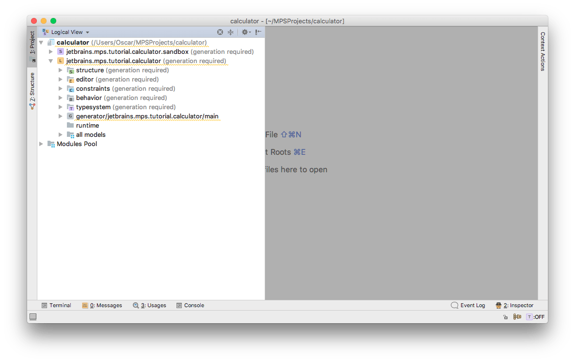
The "S"-marked tree node above it (![]() ) represents our solution, and the Modules Pool node (
) represents our solution, and the Modules Pool node (![]() ) contains a collection of all available languages and solutions, for your reference. We'll take a closer look at these items in further chapters.
) contains a collection of all available languages and solutions, for your reference. We'll take a closer look at these items in further chapters.
Let us first explore the structure of the language node. This will also help us realize the basic ideas behind MPS.
We see the child nodes of the language marked with the "M" diamond-shaped icon. They are calledaspect models. Unlike other languages where programs are usually stored in text files, in MPS they are stored inside models. Each model represents a tree ofnodes, where each node may have a parent, child nodes, properties and references to other nodes. Each node is defined by itsconcept.
Aspect models comprising our language describe different features of a language (their icons differ by color). For now, we consider the 4 basic aspect models that we will need for our language:
structure— describes the syntax of a language
editor— describes how a model written in the language looks in the editor
constraints— describes things like which name is appropriate for a node, which variable a variable reference can point to, etc
type system— describes how to compute types of nodes
Calculator concept
Let's start working on our language.
First, we need to create a top level concept, in our casecalculator. Each instance of this concept will contain input and output fields.
To create a concept, right click the structure aspect model and choose New | concept:

The concept declaration opens in the editor:
A concept declaration defines the class of nodes and specifies the structure of nodes in that class.
A node can have the following elements, which are defined in the corresponding sections of the concept declaration:
Properties store primitive values inside a node. For example, you can define a node's name as a property.
References store links to other nodes. For example, we can use them to store a reference to a local variable.
Children store aggregated nodes, i.e. nodes which are physically contained inside a current node. For example, method declaration aggregates its return type and arguments. In our case these would be input and output fields.
Other sections are quite advanced and we won't discuss them in this tutorial. You can read about them in the MPS User's Guide.
Concept declarations form an inheritance hierarchy. By default, every concept extends the BaseConcept concept (you can see it immediately after the extends keyword). You can, however, specify another direct parent instead as necessary. If a concept extends another, it inherits all properties, children, and references from its parent.
So, let's name our conceptCalculator.
Press Tab until you get to the 'instance can be root' placeholder, and press Ctrl+Space to set its value totrue. You can also type true directly, you don't have to press Ctrl+Space everywhere. This will let us create Calculator instances through the Create Root Node menu item in the Project View (right as we did for our Calculator concept itself):
We will further need to reference our calculators by name. We could create a property name inside it; however, there is a better way (and the recommended practice) to do so. We have to make our concept implement the INamedConcept interface. This concept interface contains only one property —name. MPS IDE knows about this interface and allows for more advanced support for concepts which implement it. For example, if you want to create references to INamedConcept s, their names will be displayed in completion menu; or when you explore your nodes in theProject View, you will see the names ofINamedConcepts in the tree.
Position the caret at the <none> placeholder after the implements keyword, and press Ctrl+Space (for more details about effectively using the editor, please see Appendix A):
Choose INamedConcept and press Enter:

We have defined syntax for a node. Now we need to define its aspects. Let's create an editor.
Creating an editor for Calculator
MPS editor looks like a text editor but it isn't one exactly. It is a structural editor that works with the syntax tree directly.
You might wonder why someone would want to use a structural editor when almost all existing languages are text-based. Text based languages are good until we want to extend them. Text-based languages usually have a parser. In order to make parsing deterministic, the grammar should be carefully designed, which proves almost impossible in case of language extensions. If we extend a language, we should extend its grammar, but since we don't know what other extensions might do, we can't be sure whether this grammar is sufficient. Consider two language extensions which add monetary-value support for Java. Both of them would add the money keyword. When we parse some code that uses these two language extensions, we don't know how to interpret the money keyword. Should it be interpreted as a keyword from the first language or from the second one? In case of the structural editor, where a program is stored directly as a syntax tree without intermediate text presentation, there's no such problem.
The structural editor in MPS uses cells to represent nodes. Like nodes, cells form a tree. There are several types of cells:
property cells are used to edit node's properties
constant cells always show the same value
collection cells are used to layout other cells inside of them
We want the editor for our calculator to look as follows:
calculator name
To implement such a design, we do the following (keep using Ctrl+Space):
create an indent collection cell. Indent collection layouts cells text like way.
create a constant cell and property cells inside of the collection.
To define new editor for Calculator concept you have to select Editor tab in the bottom line of editor tabs — empty tab with No Editor label on it will be displayed since editor aspect was not defined yet for this concept. You can click onto this empty editor pane and choose concept editor from the assistance menu
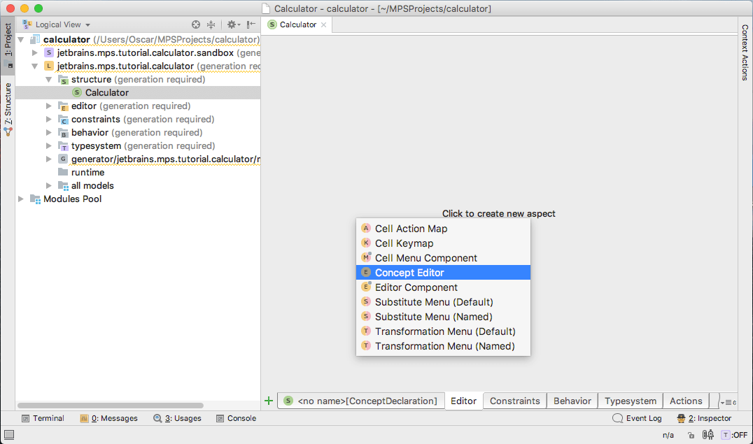
to create a new editor

Let's create a root indent collection cell. Press Ctrl+Space and choose [- there:

Now, let's create a constant cell:

and type calculator inside of it:

You can enter this constant in one step if you type: "calculator. The " symbol will make the cell a constant cell.
Now we need a property cell for the name property (from the INamedConcept concept interface). To insert another cell at the end of the horizontal list, press Enter at the end of calculator word and choose {name} in completion:

Now, when the basics have been defined, we can Build our language and try to create an instance of its concept. To build a language, choose the Make Language action from our language's popup menu in theProject View.

The code was generated, so you can create and edit instances of this concept in MPS models. MPS probably created an empty solution model for you already during the initial project creation. If you for some reason do not have a model, we can create a new MPS model in jetbrains.mps.tutorial.calculator.sandbox now: right-click on sandbox node in project tree and choose New | Model from the pop-up menu.
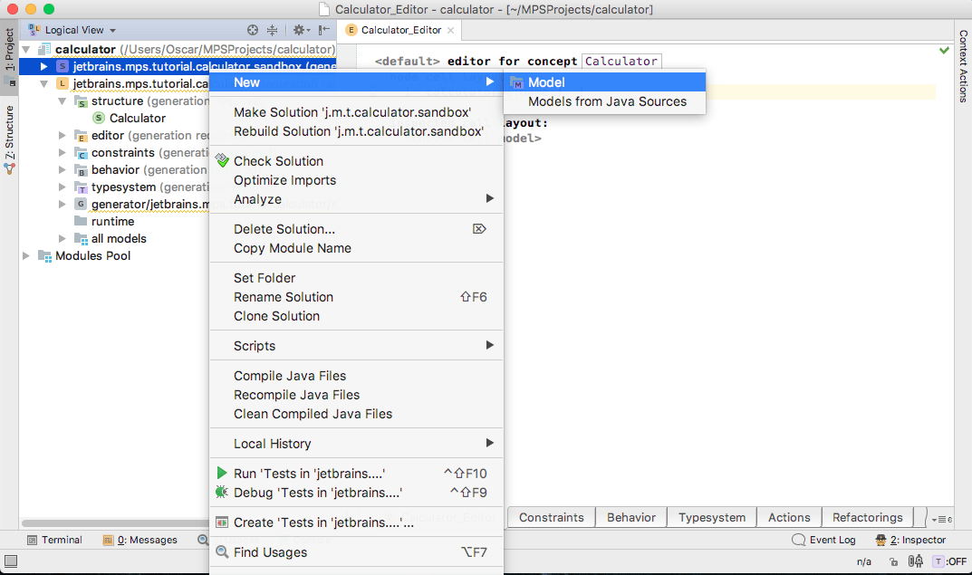
Type jetbrains.mps.tutorial.calculator.sandbox in the Model name field of New Model dialog
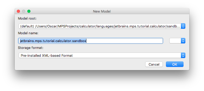
and press Ok button. In order to use jetbrains.mps.tutorial.calculator language inside this model you have to import it by pressing + button in Used Languages section of the displayed Model Properties dialog and choosing jetbrains.mps.tutorial.calculator language:
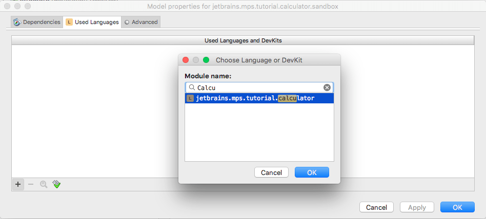
Now you can press OK in the Model Properties dialog to finally create a sandbox model and start working with Calculator instances there.
Define your first calculator
Click the sandbox model, and then choose Calculator from the New menu:

You will have a simple calculator where you can type in a name:

Type the name in the property cell. For our example, we took the MyCalc name.
As you can see, the calculator's editor is quite similar to what we have written in the editor aspect.
Input Fields
Now let's create concepts for input fields. The field will implement INamedConcept since we want to reference it in the output fields. We need it since when we reference a node, we need to see it in the completion menu. In case of INamedConcept instances, their names are correctly displayed, since MPS understands what names these instances have. It is certainly possible to reference concepts other than INamedConcept, but INamedConcept is the easiest way to do so.

Let's create an editor for it:

In order for the calculator to contain input fields, we need to adapt its structure and editor a little. Let's create a child of type InputField to Calculator with 0..n cardinality. To do so, put a caret on children section and press Enter or Insert. After that, specify InputField as a target Concept, set child name to inputField and cardinality to 0..n:

Now we add a new line to name cell. A light bulb will appear when you position the cursor on the name cell. Actions that can be invoked with a light bulb are calledintentions. There are a lot of them in different languages. In case you don't know how to enter something, in addition to pressing Ctrl+Space you can press Alt+Enter and use the corresponding intention. Now press Alt+Enter and apply the Add New Line intention.

Now we want to show a vertical list of input fields in editor. Press Enter in the end of {name} label and then press Ctrl+Space. Choose %\inputField% there:

We want input field to be placed verticaly. So, a new line should be added after every cell. This can be done with an intention: press Alt+Enter and chooseAdd New Line for Children.

Now let's make our language using the pop-up menu on the Language node in the left-hand side Project View panel (you can also press Control/Cmd + F9 to do it) and take a look at our sandbox:

The editor has been updated. Now we have the cell below the line with a name where we can add new input fields. Let's add a couple of input fields:

Output fields
Let's create a concept for output field. It doesn't need to contain a property name since we want to reference values in input fields only (compare with InputField that implements INamedConcept):

Let's create an editor for it:

Let's add a child of type OutputField to the calculator concept:

Now we change its editor. You can use copy/paste here; use Ctrl+Up and Ctrl+Down to select cells, then Ctrl+C and Ctrl+V to copy/paste. In order to paste a node after %\inputField% collection, press Ctrl+V on the closing "-)" parenthesis. Replace inputField with outputField.

We separated input fields from the output field with an empty cell. To add it, position the caret after inputField's cell and press Enter, choose constant, then using Add new line intention add line separator after this constant.

Now, let's make our language (right-click on theLanguage or hit Control/Cmd + F9) and take a look at our sandbox concept:

We can add output fields but we can't type any expressions inside it since we haven't declared anything to allow storing expressions:

Adding expressions support
In MPS we have BaseLanguage, the MPS's counterpart of Java. When we create a new language, we often extend it or reuse concepts from the BaseLanguage. Let's reuse its expression language for our output fields. To do so, we need to make our language extend BaseLanguage. Language extension in MPS means that you can use and extend concepts from extended language. We want to use the Expression concept from BaseLanguage, so we need to add it to the extended languages section. Open the language properties dialog:

Let's add BaseLanguage to the list of extended languages. To do this, select the Dependencies tab, click the Add button (![]() ) and choose jetbrains.mps.baseLanguage. Then select Extends from the drop-down box forScope.
) and choose jetbrains.mps.baseLanguage. Then select Extends from the drop-down box forScope.

BaseLanguage contains an Expression concept. It represents expressions of the form: "2", "2+3", "abc+abc", etc. It's exactly what we need for our output field expression. Let's take a look at it. Press Control/Cmd + N and choose Expression from the BaseLanguage there:

Expression itself is an abstract concept. Let's take a look at it:

An expression has no properties of its own. So let's take a look at its subconcepts in order to understand which kinds of expressions we have in MPS. Choose 'Show Concept in Hierarchy' action in popup menu:

As you can see, there are a lot of different expressions in different languages. Expression is extended very widely:

Now let's add a child of type expression to the OutputField:

And change its editor accordingly (you can use Ctrl+Space here):

Now let's make the language (right-click on the Language or hit Control/Cmd + F9) and take a look at what we've got:

You may need to add BaseLanguage to the dependencies of your model:
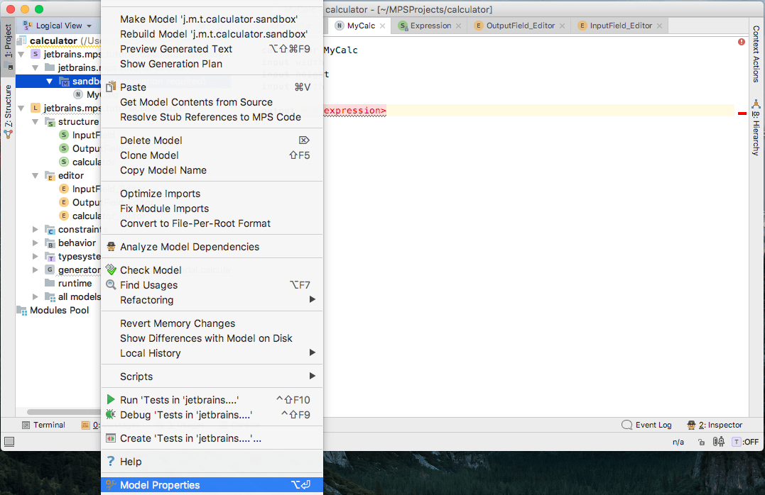
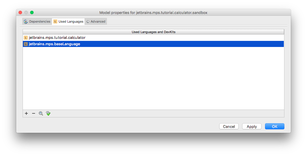
Now we can type expressions in output fields, but, unfortunately, we still can't reference the input fields there:

Extending Expressions concept
In order to support references to input fields, we need to create our own kinds of Expression. Let's name it "InputFieldReference" and make it extend Expression. Let's create it:

We added a reference here. It has type InputField, and 1-cardinality. Concepts, which have exactly one reference of 1-cardinality, are called smart references and have special support in the editor. You will learn more about it a little bit later. Now let's create an editor for it. Choose %\field%->:

And inside of the rightmost cell, choose {name}:

We use %\field%-> {name} to show a name of a node that is referenced by the field reference.
Now make our language, and take a look at what we've got. We can now type input field for our nodes:

This is possible because of smart references. Here's how they work. If a concept which is a smart reference is available in the current context, MPS takes a look at a list of possible nodes, which it can reference, and adds one completion item for each such a node. That's why we have width, height, depth in the completion menu.
Creating a generator
Let's create a generator for our language — we want to generate an implementation in Java. MPS might have created one already for you, but if it didn't, choose the New->Generator menu item in the Language pop-up menu:

Leave generator name empty:

Now your language contains a new generator:

The entry point of a generator is a mapping configuration. It specifies which nodes are transformed and how:

Deciding what to generate
Before we start developing a generator, we need to think about what kind of code we want to generate. We might want to generate something like this:
public class Sandbox extends JFrame { private JTextField myInput1 = new JTextField(); private JTextField myOutput = new JTextField(); private MyListener myListener = new MyListener(); public Sandbox() { setTitle("Sandbox"); setLayout(new GridLayout(0, 2)); myInput1.getDocument().addDocumentListener(myListener); add(new JLabel("Input 1")); add(myInput1); add(new JLabel("Output")); add(myOutput); update(); setDefaultCloseOperation(JFrame.EXIT_ON_CLOSE); pack(); setVisible(true); } private void update() { int i1 = 0; try { i1 = Integer.parseInt(myInput1.getText()); } catch (NumberFormatException e) { } myOutput.setText("" + (i1)); } private class MyListener implements DocumentListener { public void insertUpdate(DocumentEvent e) { update(); } public void removeUpdate(DocumentEvent e) { update(); } public void changedUpdate(DocumentEvent e) { update(); } } public static void main(String[] args) { SwingUtilities.invokeLater(new Runnable() { public void run() { new Sandbox(); } }); } } Here's how our application looks when executed:

Now let's implement it.
Implementing generator
Let's first create a skeleton for the main class. We need to create a class with the update method, main method and DocumentListener that invokes the update method etc. Let's choose a new class from the new menu:

And you will get this:

As you can see, MPS added a root template annotation on the top of a class. Every non generator language node inside of generator model is treated as template. Every template should have an input node, the node which is used to generate from. A root template annotation is required in order to specify the type of this input node. Let's set input to Calculator:

Let's give a name to the class:

Now let's create a rule in mapping, which will generate a class with this template from each calculator in our input model. Let's add this to the mapping:

This rule instructs to take each Calculator from the input model and apply to it to theCalculator template. Let's rebuild our language (right-click on the Language and chooseRebuild Language) and then preview the text generated from our model:

We will obtain the output into a new editor tab, labelled with the name of the generated Java file:

As you can see, there is one class with the name CalculatorImpl in the output.
Implementing the template
Let's make our template use the name of the Calculator node that we give it in the source model. Put the caret on the class name. Press Alt+Enter and choose theAdd Property Macro:

Property macros allow us to specify a value for a property, which depends on an input node. Let's type this into the inspector:

Now let's rebuild the language again (right-click on the Language and chooseRebuild Language) and then preview the code generated from our sandbox model. You will see a class with the correct name corresponding to the name of the Calculator instance:

Now, let's enter the rest of the class skeleton into the template. To do so, we need to import models corresponding to Java classes. If one model imports another, an importing model can reference nodes from another. In order to simplify interoperation with Java, MPS can create models corresponding to jar-files or folders with classes. These models have names of the package.name@java_stub form and can be added from the model properties dialog:

Let's import javax.swing@java_stub, javax.swing.event@java_stub, java.awt@java_stub and javax.swing.text@java_stub models into the template model:

Let's inherit our class from JFrame, create a main method, a documentListener field, and an update method in the Calculator template. Note that you should create the update method before you create calls to it.

Now let's create code that will set up a frame for us:

Put a property macro on "Calculator" string and add node.name to the inspector so as the title reflexes the name of the calculator:

Now let's create a visual text field component for each input field. First, we need to add a single text field of the JTextField type:

Now we'll make sure such a text field gets created for each calculator's input field. Let's select the whole field declaration (use Ctrl+Up shortcuts) and choose Add Node Macro:

We get the following:

Choose loop from the completion menu:

The Loop macro allows you to repeat a construct under macro many times: one time for each node in a collection that is returned by a code in inspector.
In the loop's inspector type the following:

This means that we want to have a field in a class for each inputField that we have in the source calculator.
Let's give each visual text field a unique name. We need to add a property macro to its name and type this piece of code inside the macro:

This code will give our variables unique names like inputField_a, inputField_b, etc.
We also need to do the same for outputFields:

The only difference is that we use node.outputField in $LOOP$ and use "outputField" as a base name. In order to make your changes available to MPS, make the language.
Let's make our sandbox and take a look at what we have:

As you can see, the fields have been generated. Now we want to add these fields to the visual frame. Type this:

Essentially, you create a BlockStatement (code wrapped in {}), so as we can treat the content of the BlockStatement as a single unit belonging to a single InputField. Then we can easily repeat the block for each calculator's InputField. Surround the block and the code inside it with a $LOOP$ and use node.inputField as the value in the inspector:

Add a property macro to the JLabel's constructor's parameter so that the label will have the same text as the corresponding input field's name:

The situation is more complicated with creating a reference to a field declaration, in which the current field is stored. From the reference to an inputField, we need to generate a reference to the corresponding JTextField generated from current inputField. To do so, we need to label the field declaration and use this label to find the field.
Go to mapping and add this:

Now we have a storage for generated FieldDeclarations indexed by the original InputFields. This means that the inputField label will reference a node of type FieldDeclaration generated from the InputField. Now let's add the label to the generated field's LOOP macro:

Now we need to change the reference to an inputField to a reference found by using the lookup via the label. In order to do so we need to add a reference macro to the field reference:

Go to the inspector and type this:

You will have:

Do the same with the second reference:

Now, let's make our language (right-click on the Language and choose Rebuild Language) and take a look at what we get generated from our sandbox model:

As you can see, the references are set correctly.
Now let's do the same thing with output fields. Again, we need to create the initialization code, and surround it with a $LOOP$ macro. Create a label for field declaration and put it on outputField's $LOOP$. Then we need to use this label to create a reference. Your code in the template should look like this after making these changes:

Now let's implement the only thing that's left: the code that updates the result with a calculated value. We want to have something like this:
public void update() { int i1 = 0; try { i1 = Integer.parseInt(myInput1.getText()); } catch (NumberFormatException e) { } myOutput.setText("" + (i1)); } We create an int local variable for each input node and assign it a value in that field. Let's create a loop macro for such variables. Make sure that ";" is inside the $LOOP$ macro:

Let's generate a unique name for each of these variables:

Let's initialize these variables. In order to reference our variables, we need to create yet another label:

And assign it to the local variable declaration. To do so, you need to surround the local variable with a $MAP_SRC$ macro. In most cases, this macro is used just to add labels to nodes, which we want to reference and which don't have any other macros associated.
Make sure to select LocalVariableDeclaration, not LocalVariableDeclarationStatement. To check this, take a look at the semicolon. If it's outside of the macro bracket, then choose the right node:

Another LOOP will be needed to properly initialize these local variables with values from the calculator's input fields. First, add a try ... catch block. You will have this:

Surround it with a LOOP macro:

Please make sure the whole statement (the line including the ending semicolon) is wrapped by the LOOP macro. Then create reference macros and use the labels to find corrent targets (i.e. LocalVariableDeclarations and InputFields, respectively) for these references. With local variable:

With field reference:

Now we need to set output values into the text fields that represent the calculated outputs. Type the following code:

Surround it with a LOOP macro:

Again, please make sure the whole statement including the ending semicolon is wrapped in the LOOP macro. Then add a reference macro to the outputField:

Now we need to set the text so that it will display the calculated result. So we need to generate the output field's expression to where the null value is. Remove null argument of setText() method and type: "" + (null). Use Ctrl+Space on each step. We add parentheses here to make sure that the output code will be correct. If we didn't have parentheses and expression is 2—3, the output code will be "" + 2 — 3, which isn't correct. On the other hand, "" + (2 — 3) is correct:

Add a node macro to the null value and change it to a $COPY_SRC$ macro. $COPY_SRC$ macro replaces a node under the macro with a copy of the node returned by the code in the inspector. We return node.expression:

The only thing that's left is handling the InputFieldReference. We don't have a generator for it yet. We need to replace the reference with the value retrieved from the JTextField corresponding to the refered input field. So assentially the corresponding i variable stored in the LocalVar label. To create a generator for an InputFieldReference, we need to define a reduction rule. Reduction rules are applied to all the nodes that are copied during generation, for example, in $COPY_SRC$ macro. Let's create the corresponding reduction rule in the mapping configuration:

Since the template will not be very long, we will use an in-line template with context. Chose <in-line template with context> from completion list.
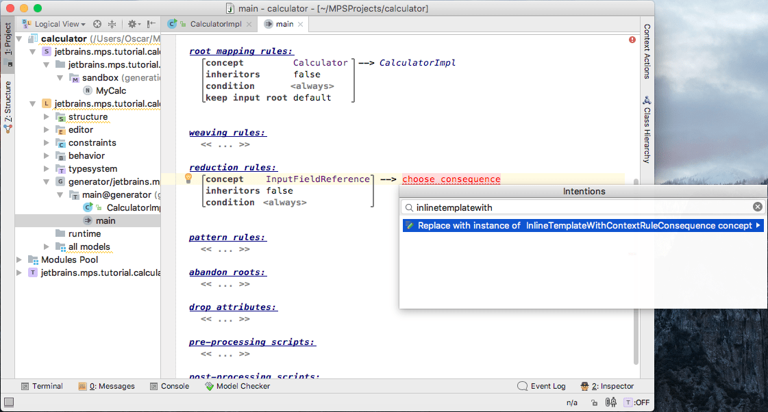
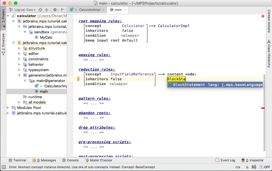
We translate the InputNodeReference to a local variable reference, so we have to create valid context node that would contain such a local variable reference. Let's use BlockStatement as a context node:
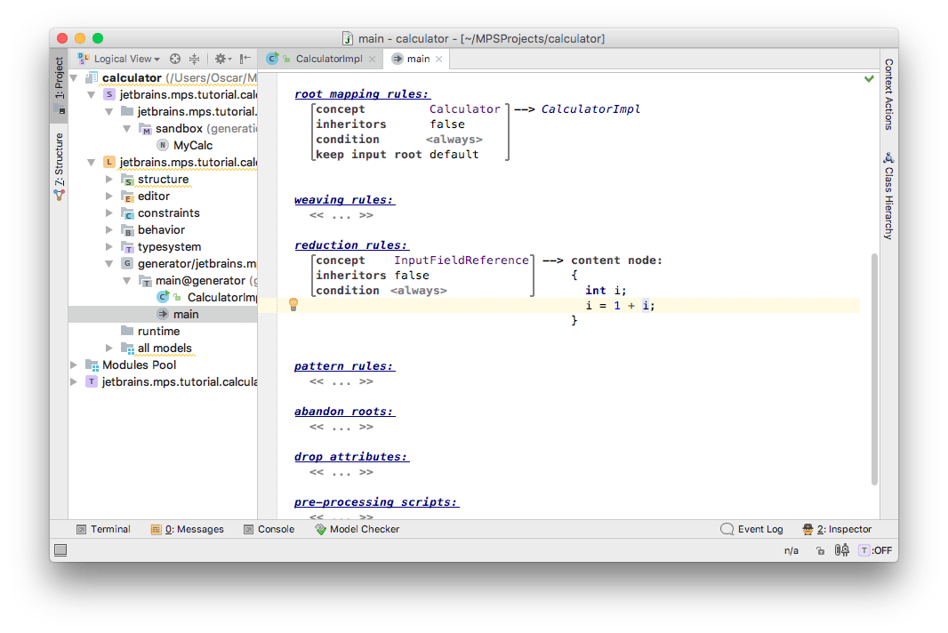
Inside this BlockStatement let's define local variable i and create simple expression referencing it:
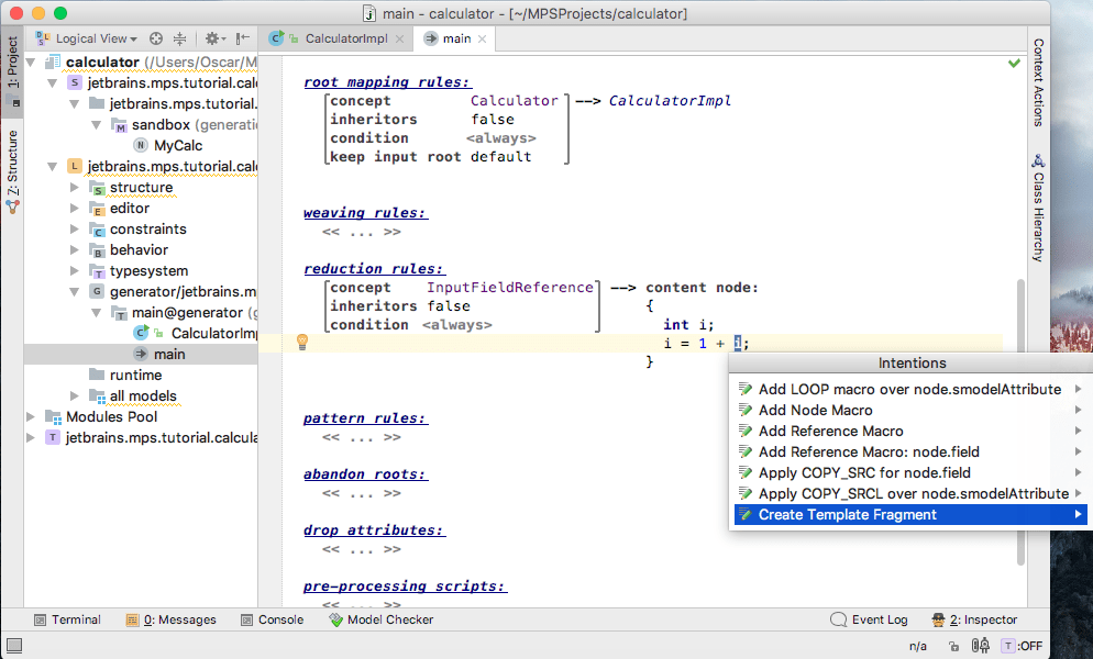
This reference to a local variable i is what we will use as a result of the in-line template, so we should mark it as a template fragment. Press Alt+Enter and choose "Create Template Fragment" intention:
Now let's create reference macro for this local variable reference:
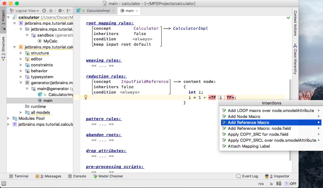
and specify proper reference query to get the correct i fromLocalVar:
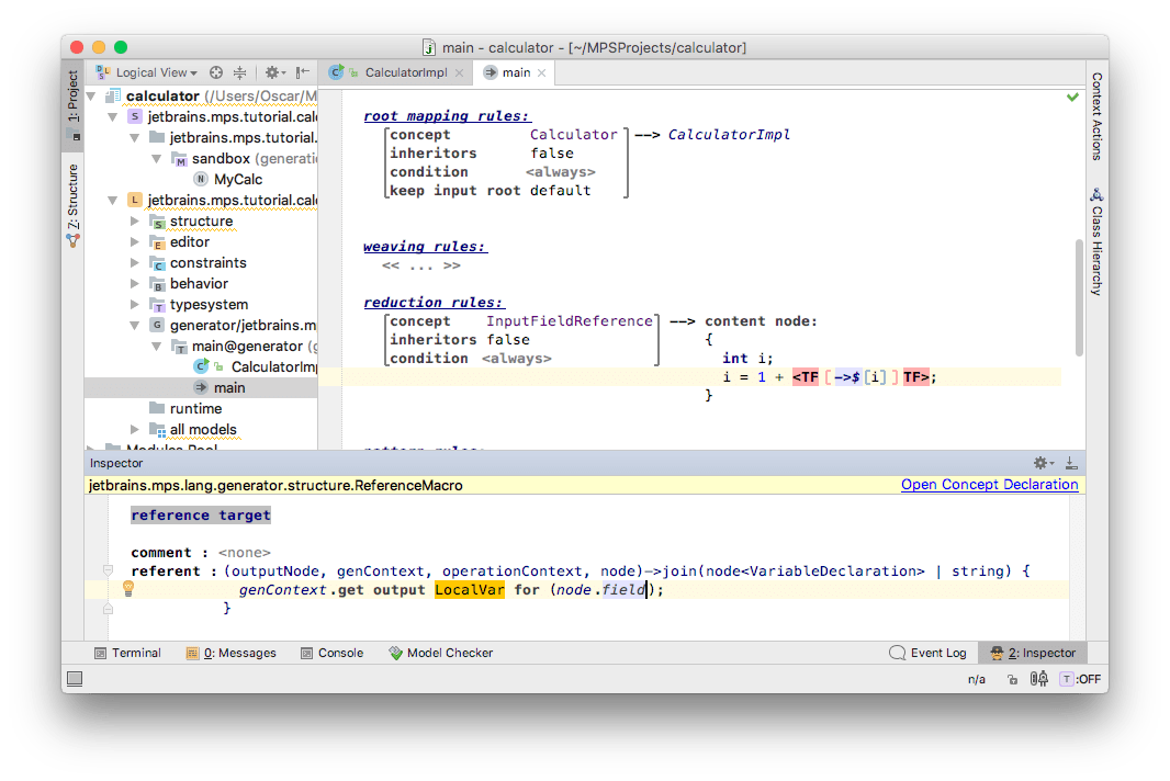
Now, let's rebuild our language (right-click on the Language and chooseRebuild Language) and take a look at what happens with the sandbox model. As you can see, MPS generates exactly the code that we wanted:

Entering Salary program
Having finished the language and its generator, we can enter salary program. Here it is:

Running generated code
In order to run code, you need to make your solution model:

Your sources will be available in solution source_gen directory. (Don't forget to switch to File System View):

You can run them with your favorite Java IDE.
We finished the main part of our language, now let's do some polishing.
Creating a scope for InputFieldReference
If we create another Calculator root in the sandbox model, we will be able to reference input fields from the first calculator, which isn't correct:

Let's fix it. To do so, we need to define the scope for the InputFieldReference concept. We do that by defining a constraint: open InputFieldReference, go to the Constraints tab, and create a constraints root for it: We will use the new hierarchical (inherited) mechanism of scope resolution. This mechanism delegates scope resolution to the ancestors, who implement ScopeProvider. Our InputFieldReference thus searches for InputField nodes and relies on its ancestors to build a list of those.

Add a referent constraint and choose field as its link:

Now let's create a scope for this link. Go to the scope section and hit Ctrl+Space. We need to specify how to resolve elements that the InputFieldReference can link to:
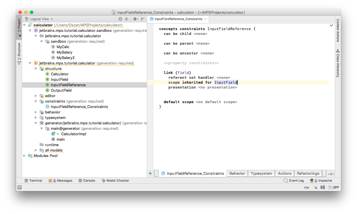
Once we have specified that the scope for InputFieldReference when searching for an InputField is inherited, we must indicate that Calculator is a ScopeProvider. This ensures that Calculator will have say in building the scope for all InputFieldReferences that are placed as its descendants.
The Calculator in our case should return a list of all its InputFields whenever queried for scope of InputField. So in the Behavior aspect of Calculator we override Ctrl+O the getScope() method:
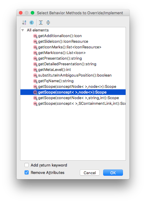
If Scope remains unresolved, we need to import the model Ctrl+R that contains it (jetbrains.mps.scope):
We also need BaseLanguage since we need to encode some functionality. The smodel language needs to be imported in order to query nodes. These languages should have been imported for you automatically. If not, you can import them using the Ctrl+L shortcut.
Now we can finally complete the scope definition code, which, in essence, returns all input fields from within the calculator:

A quick tip: Notice the use of SimpleRoleScope class. It is one of several helper classes that can help you build your own custom scopes. Check them out by Navigating to SimpleRoleScope Control/Cmd + N and opening up the containing package structure Alt+F1.
After you make the language (right-click on the Language and choose Make Language), you will no longer be able to access a field from the first calculator in the second one:

But you can still access fields in the first calculator:

Creating a type system rule for InputFieldReference
We can now type something like this:

This code isn't correct because width must be Boolean, since it's used as part of a ternary operator's condition. In order to make this error visible, we need to create a type system rule for our concept. Let's do it. Open the InputFieldReference and go to Typesystem tab. Create an InferenceRule there:

Our typesytem engine operates on type equations and inequations. Equations specify which nodes' types should be equals. In equation, specify which nodes' type should be subtypes of each other. We need to add an equation that states that the type of our reference is always int. Let's define equation. Choose the equals sign in the completion menu:

Choose typeOf in its left part:

Type 'inputFieldReference' inside of typeof:

Choose <quotation> on the right part of the equation:

Quotation is a special construct that allows us to get a node inside of quotation as a value. Usually nodes we want to create are quite complicated, so creating them with sequential property/children/reference assignments is an error-prone and boring activity. Quotations simplify such a task significantly.
Type IntegerType inside of it:

Now our rule is complete:

Let's make the language (right-click on the Language and choose Make Language) and take a look at code with error:

It's now highlighted. You can press Ctrl+F1 and see the error message: "type int is not subtype of Boolean".
How to use the MPS editor
Despite looking like a text editor, MPS editor isn't one exactly. Because of this, working with it is different from working with text editor. In this section we will describe the basics of working with MPS editor.
Navigation works similar to that of a text editor. You can use the arrow keys, page up/down, and home/end, and they behave the same way as in text editors. Selection works differently: you can't select an arbitrary interval in the editor, since there is no such thing in MPS. You can only select a cell or a set of adjacent cells. To select the parent of the current cell, press Ctrl+Up. To select a child of the current cell, press Ctrl+Down. If you want to select adjacent cells, use Shift+Left and Shift+Right.
Unlike text editors where code completion is optional, MPS gives you this feature out of the box. You can press Ctrl+Space almost everywhere and see a list of possible items at the current position. If you want to explore a language's features, the best way to do so is to use this shortcut in the place which you are interested in and look at the contents of the completion menu.
Another commonly used feature of MPS is intentions. Intentions are actions which can be applied to a node in the editor. You can apply intentions if you see a light bulb in the editor. If you press Alt+Enter, the light bulb will be expanded to a menu so you can choose the actions you want.
In MPS we often want to add a new element to a place where multiple such elements are possible. For example, we might add a new statement in a method body, a new method in a class declaration, etc. To do so, you can use two shortcuts: Insert and Enter. The former adds a new item before the current item. The latter adds a new item after the current one.